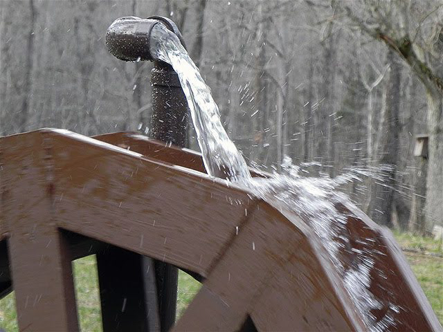
We had build a previous waterwheel (picture below) from the great video of "bhill671" And it taught us a lot. However, there were areas we wanted to improve:
1) The axle was not sufficiently rigid and anchored for the forces exerted on it,
2) It was difficult to balance
3) The frame was not stiff enough to compensate for the vibrations of the wheel
4) The buckets let the water leak out too fast and much of the potential power was lost. Although no load is applied to the waterwheel I though it would be more elegant to use as much of the potential energy as possible.
So the first step was to design a waterwheel and the support.
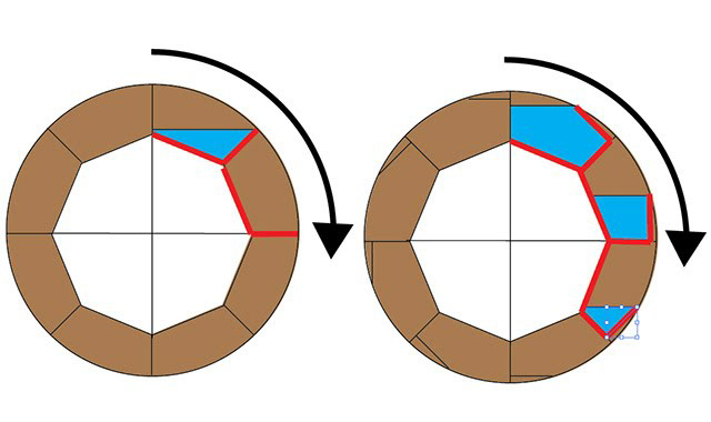
The power of a waterwheel depends on the kinetic energy of the water entering the buckets and the potential energy of the water. The kinetic energy is small in our case. The potential energy depends on how fast the water leaks out of the buckets.
If the bucket is simply a radial division, as on the left drawing, the water leaks out totally after just a quarter of rotation and thus much less then half the energy is recovered. On the right the bucket is closed further and it is not until half a rotation that the bucket empties.
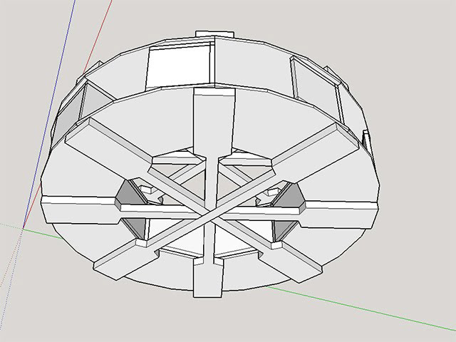
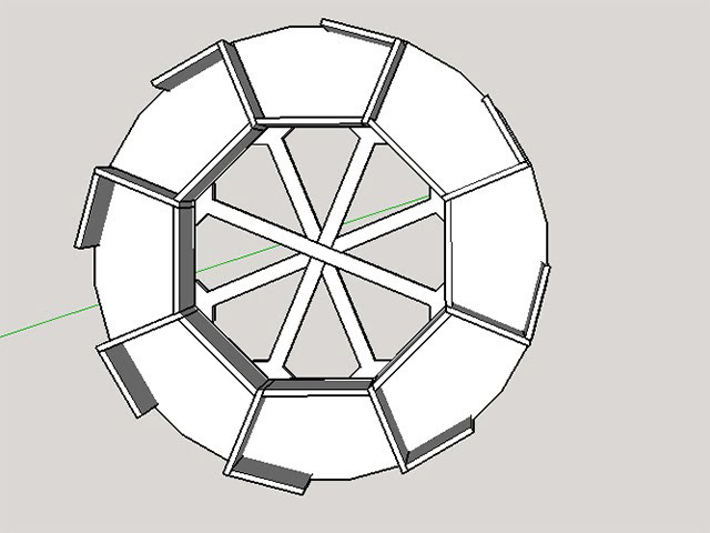
This was the initial design we came up with:
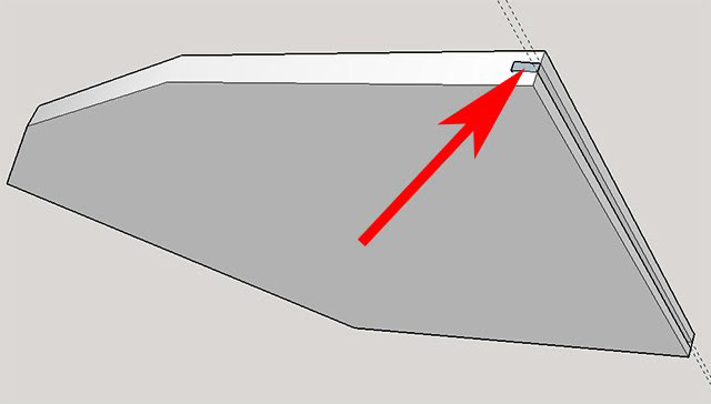
And the cross-section of the buckets:
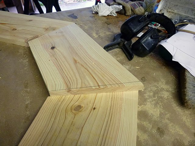
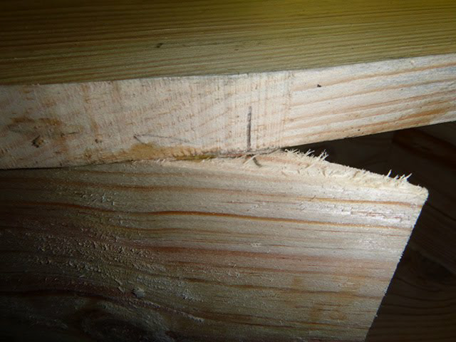
To make the wheel sturdy but not too heavy we cut 1" (2.5 cm) thick wood and we connected all the segments with a thick spline, this provides a very strong join between two adjacent segments:
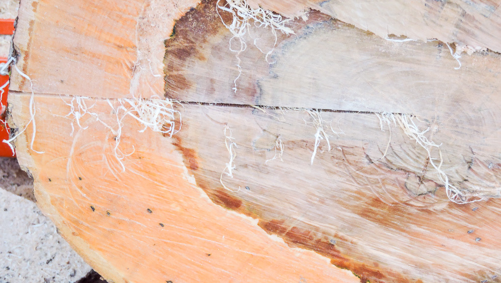
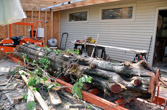
Time to go to the forest and cut a tree and bring it to the sawmill:
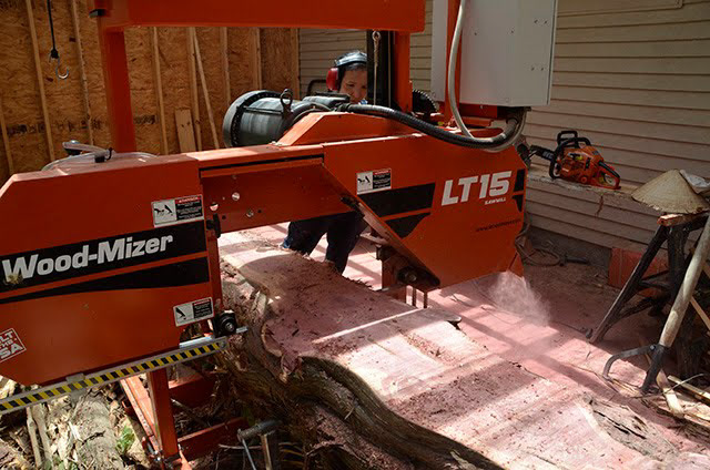
...and slice it ! Note the concentration on Thao's face !
... More relaxed as the boards shape up !
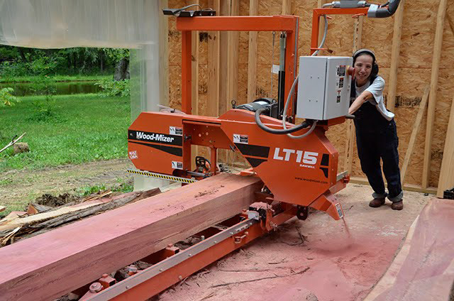
Actually since big cedar trees are not a very common the farm we also cut some loblolly pine which we ended up using. Thus the change from pink wood to white :).
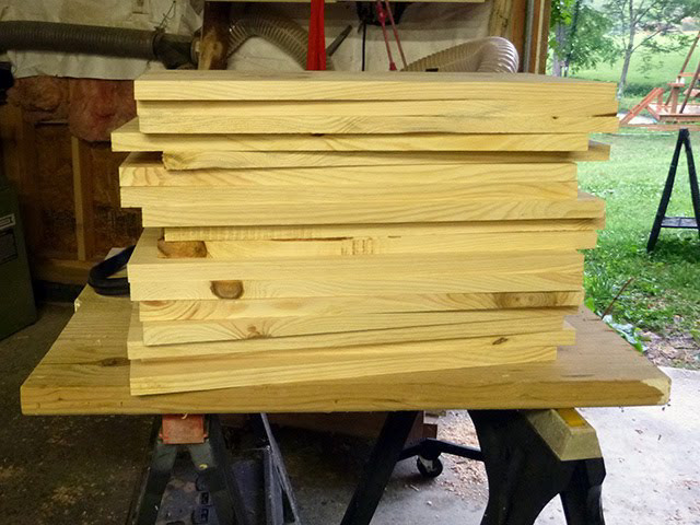
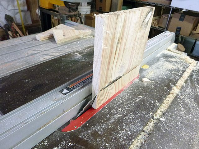
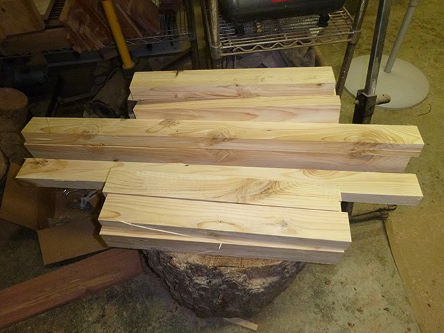
The boards are then cut in short segments to make the sides:
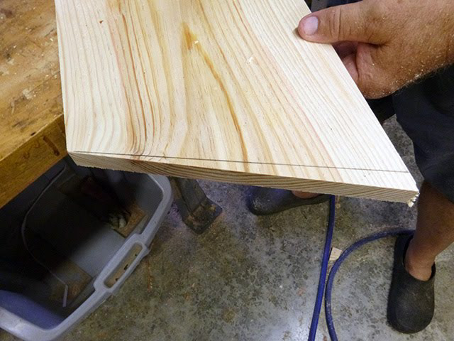
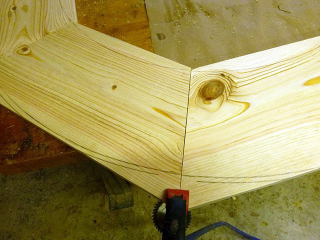
Both ends of each board is cut at 22.5 degree so that 8 of them make an octagon:

It turned out in fact that although the 90 degrees cut are properly set, there was a 3-5 degrees inaccuracy when all 16 cuts were summed up.
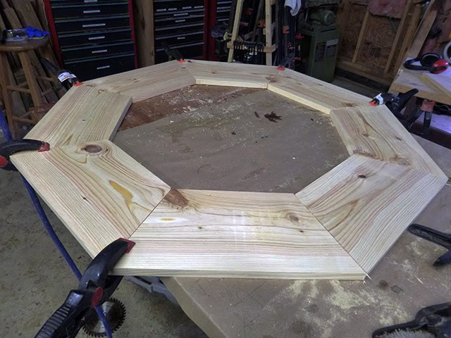
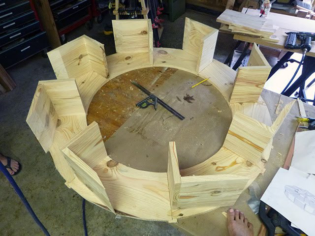
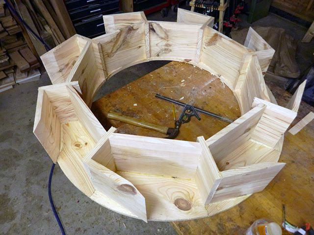
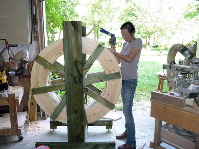
First attempt at dry-fitting the first side, it took some time to figure out how to prevent all the pieces from wiggling around! Finally, the clamps worked pretty good.
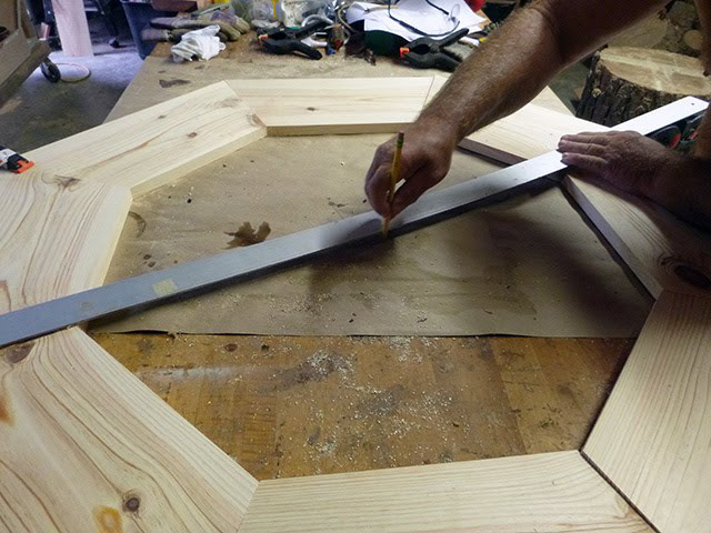
The next task was to draw the inner and outer circles, which required finding the center of the octagon. Tracing some diameters on a piece of paper worked good:
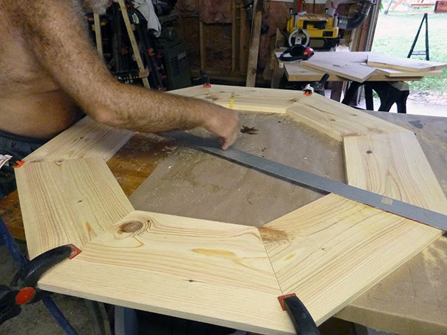
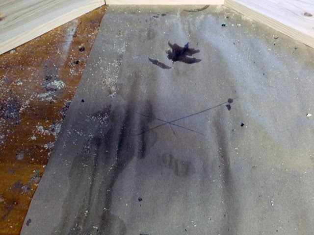
This rudimentary technique provided a remarkably good estimate of the center ! The lines almost intersect on the same point:
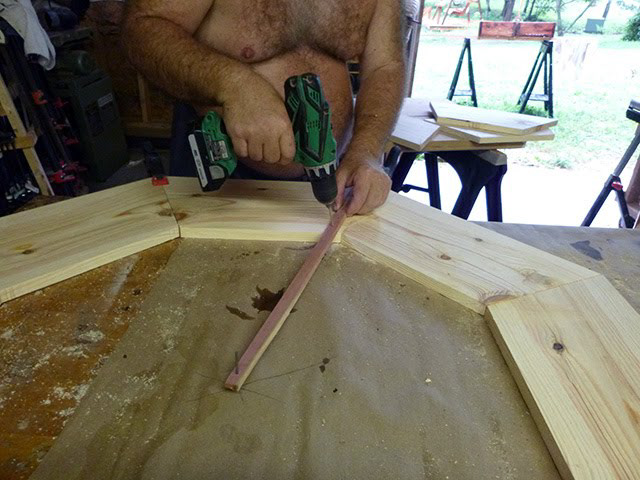
The we used a scrap stick, with a hole at one end to serve as pivot:

A small hole was drilled at the distance of the smallest and largest circle:
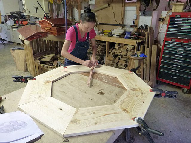
And Thao traced both circles:
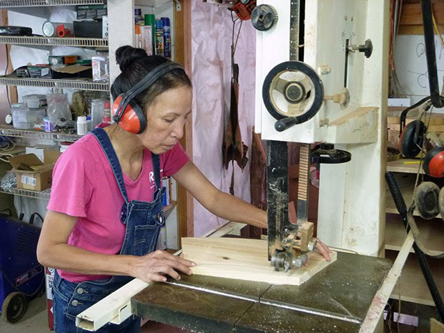
Thao then cut all those curves on the band saw:
While I prepared the splines and the groove the fit them.
It was not intuitive to me but the splines had to be cut across the grain and not along the grain as the force they needed to resist was a separation force and if cut along the grain, they would have offered no resistance:
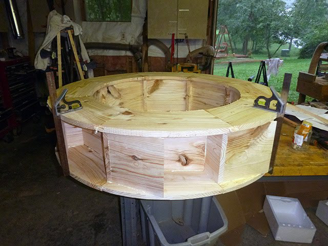
The splines glued in place:
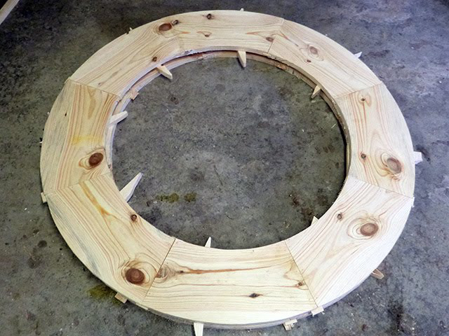
And finally both face of wheel drying and stacked with sticker boards:
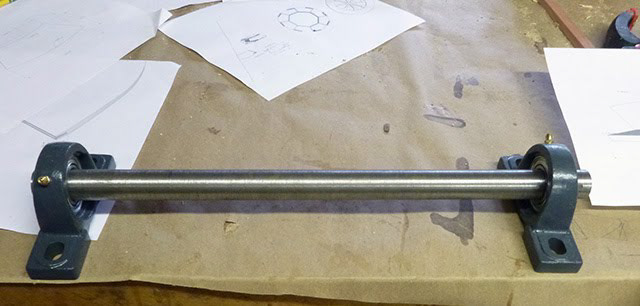
We got a 1" (2.5 cm) steel bar TGP (Turned, ground and polished), 18" (46cm) long to serve as the axle. Quite heavy and guaranteed not to bend :). Also some sturdy "pillow block ball-bearing". There was a 5 thousandth of an inch (0.12 mm) difference in size between the steel bar and the ball-bearing so I had to make some tools to attach the bar on the wood lathe and thin it by just a hair. Incredibly, since I have no metal working tool, it worked with just some hard carbide sanding paper, and it fit into the ball-bearing.
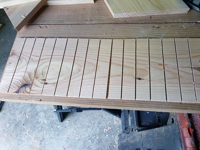
Time to cut the parts for the buckets
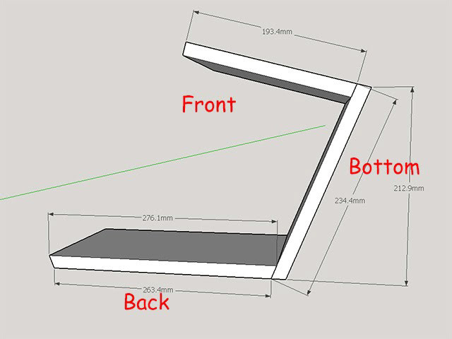
The "backs" have both ends cut at 22.5 degrees also:

And to reduce splashing I cut a 15 degree lip on the fronts
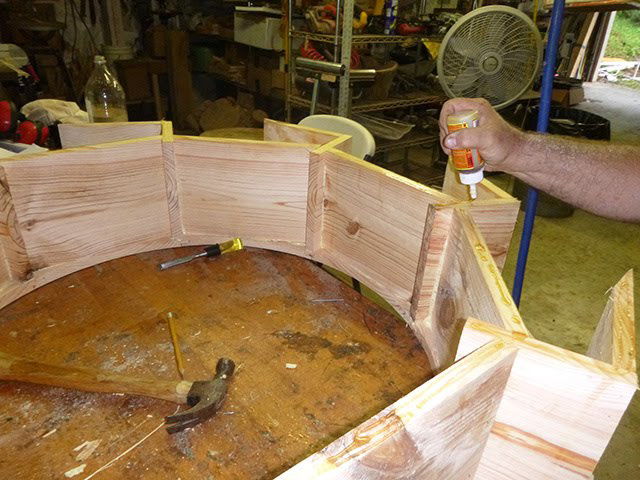
The fronts and bottoms are attached together and positioned over the splines
Then the bottoms are fitted in between. All with "Gorilla" glue that is very strong and nicely fills small gaps. Brads prevent the parts from moving while the glue sets.
Aligning the top side over the bottom side proved challenging. How to prevent small offset that would unbalance the wheel. Just eyeballing did not seems sufficient.
Ultimately the solution was to place 2 "square" (those metal tools) at 90 degree position to each other. When then touched both wheels top and bottom, the alignment was as good as we could get.
We then marked the location carefully so that we could lift the top wheel, ...
... put the glue and reset the top wheel in the exact position.
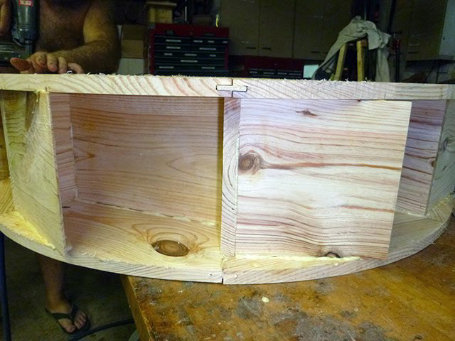
All parts are stabilized with brads, and the alignment over the spline joint is good.
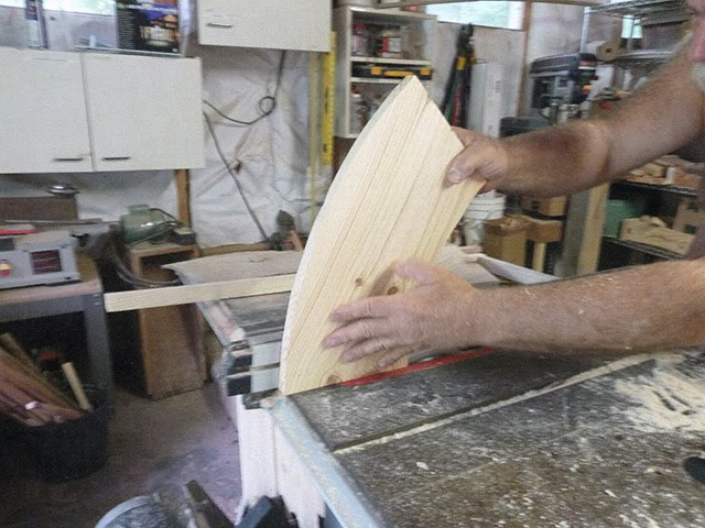
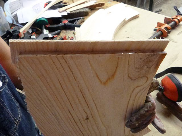
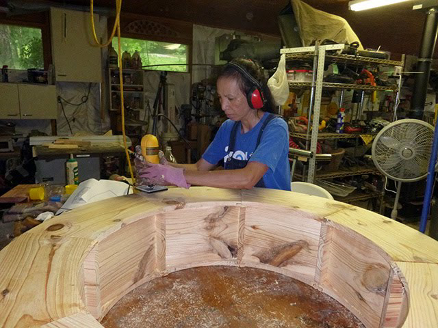
Thao then rounded the edge of the wheel, just to make it prettier:
Time to work on the hub. I first though of laminating a bunch of boards to get the right thickness, but since we had an old Cedar stump I decided to work with that:
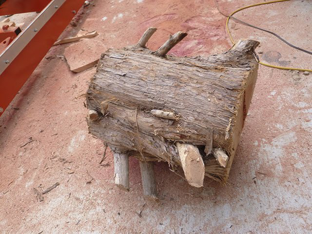
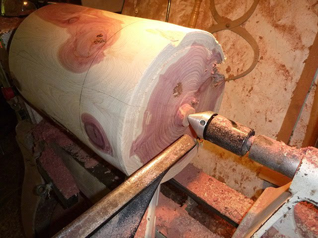
Trimmed the branches and loaded on the lathe:
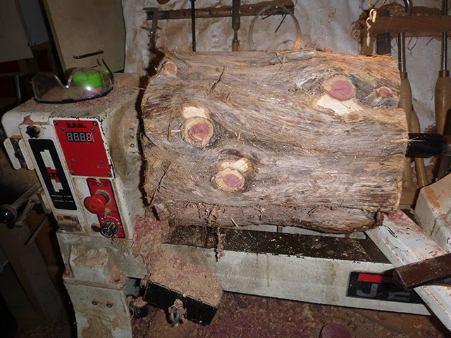
And started to "round" it:
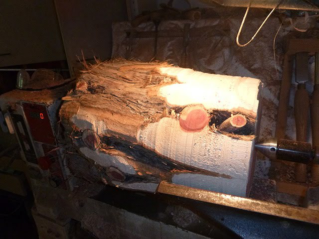
I wanted to keep the hub as massive as possible so I was OK with slight surface "imperfections" :)
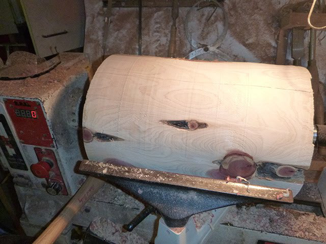
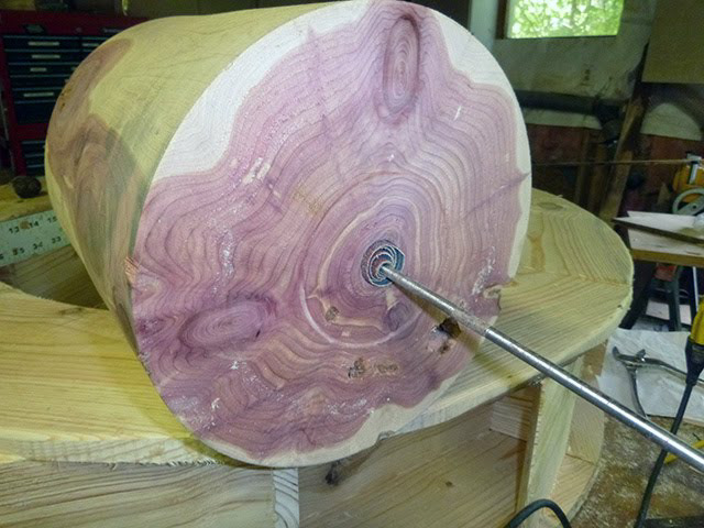
The correct length is marked and the long process of drilling the center to fit the axle is started. First with a 1/4" then 1/2" then 3/4" and finally with 1" bits.
Unfortunately the 1" bit was just a hair thinner then the 1" axle ! I did not want to pound the axle in place as 1) I did not want to damage the end, and 2) I did not want to possibly split that large hub. The solution was to duct tape some 30 grit sand paper on a thin metal rod and progressively sand the inside of the hole.
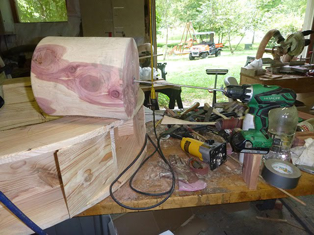
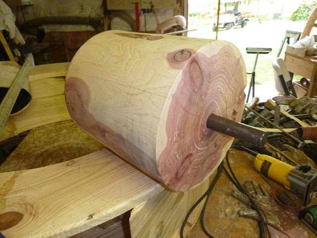
Victory ! The axle fits perfectly (hard friction) into the center hole:
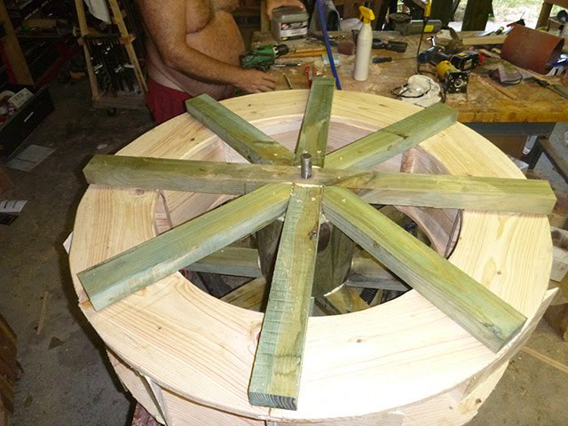
We then cut the rays that will attach the "wheel" to the "hub". One long one on each side will go across and be perforated to allow the axle to fit through. Then 2 shorter ones cut at 90 degrees will be placed at 90 degree of the "long" ones. Finally 4 more with their end cut at a double 45 degree will be fitted in between the first four rays.
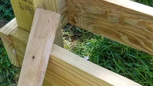
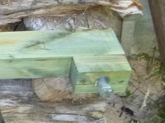
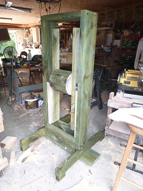
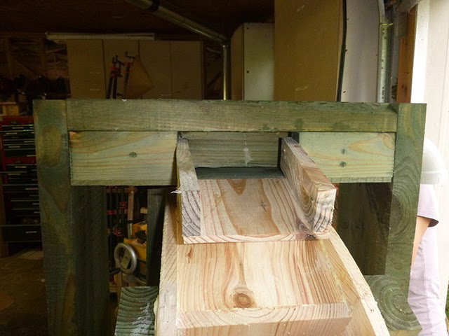
Time to design the support. It has to be rigid, so I wanted a frame that totally surrounded the wheel. It also had to have adjustable legs as it will be placed on an irregular stone. So we cut some 2 by 8 inch (5 by 20 cm) beams for the vertical supports and 3 stabilizer blocks.

To make the adjustable legs, I made a large hole to fit a large nut, and followed with a smaller hole inside so that the bolt can be recessed or expanded. The nut is simply fit by compression (it is hexagonal and the hole is a hair smaller circle). Perfect fit!
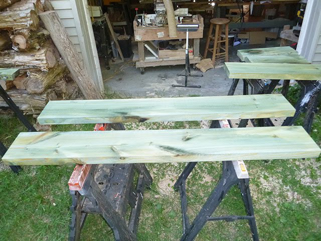
Since we used pine, which is prone to rot, we liberally painted it with a solution of Copper Naphthenate and Monoethanolamine which give it an ugly green look, but hopefully will improve longevity.
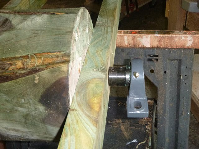
The hub fitted with the long rays on each side. The tolerances were so tight we had to use pipe clamps to squeeze the rays in position.

With the metal collars (to prevent the axle from sliding in the hub center) and the ball-bearing.
Testing the fit, it does !
Now a critical stage: fit the wheel to the hub and keep it centered !
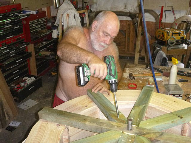
The "long" rays, the perpendicular ones and the double 45 degree in between. All generously glued ...
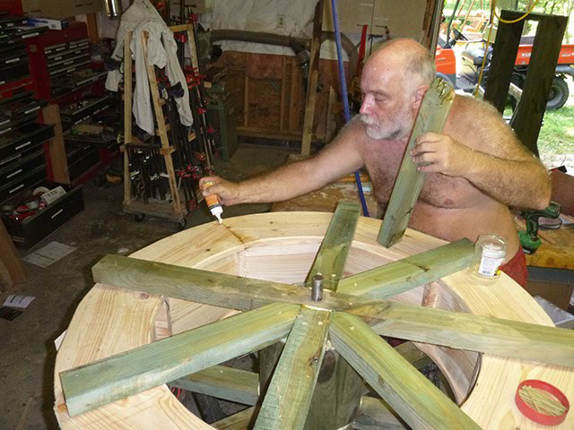
... And screwed with 3" (75 mm) deck screws.
Flipped over and doing the second side:
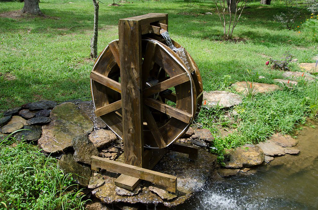
In the frame! It spins perfectly !

Thao carefully fills all possible cracks:
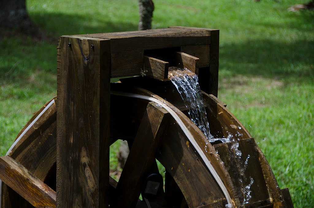
Adding the flume to have the most laminar flow possible:
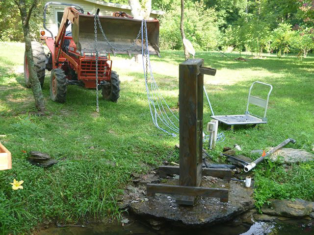
Moving the big monster in place with the tractor. This wood is just cut and therefore very heavy. I though that there was really no need to let the wood dry has it will constantly be wet by the spray. Thao also stained the wood to make it prettier and more waterproof. Of course, all end-grain has been very carefully sealed.
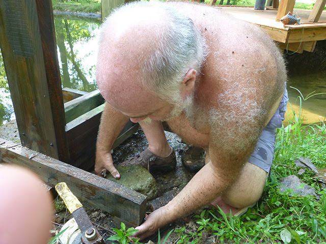
Adjusting the leveling feet with the wrench.
Testing the water connections (nothing glued since this is low pressure system), and the laminar flow.
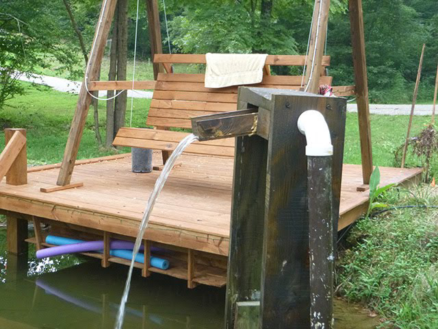
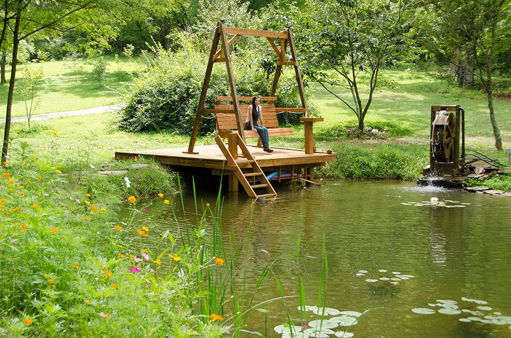
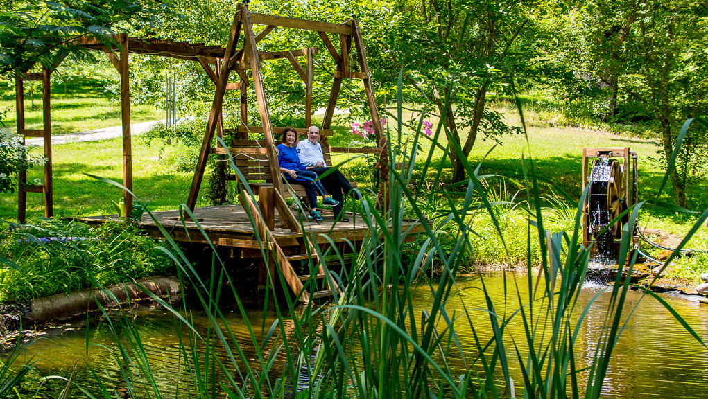
The final waterwheel:
Note the ribbon of water as it folds from one bucket onto the other. That white "cable" is a solar light rope for nighttime decoration (I am not immune to Harbor Freight flyers :( )
Thao resting in the peaceful surroundings (actually this is a staged photograph as she is always running around